Congo Bongo Repair
This is a 2 board version of Congo Bongo with Rev C ROMs installed. The pcbs were complete, but I noticed the sockets for ROMs 14,15,16 on the video board had green corrosion on the pins. After applying power, video was corrupt, but the game logic was running.
EPROMs
I pulled all the EPROMs and cleaned the chips and the sockets. I dumped the data from the chips and compared the data to the MAME set. Most of the ROMs were good, but ROMs 14,15,16 from the video board and ROM 17 from the control board were corrupt. I programmed and installed new replacements for the faulty chips.
Even after replacing ROM 16, its VCC pin (28) was only receiving 2V DC. This was one of the sockets with green corrosion on the contacts, and several attempts at cleaning failed to make an improvement on the voltage reading.
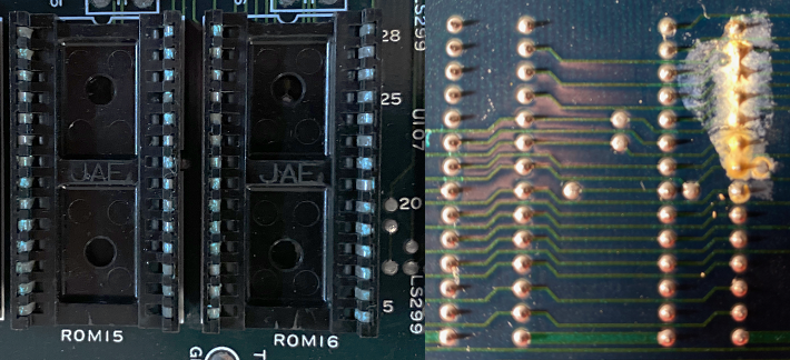
I desoldered and replaced the socket. VCC then measured correctly at 4.96V. The video was getting better, but still needed work.
ROM 5 on the control board was behaving erratically and occasionally probed as if it was out of circuit. I resocketed it, and it starting pulsing, but I was still seeing odd behavior, and it was producing different results when manually applying pressure to the chip. I pulled it again and dumped its contents. Now it was giving me faulty reads. I replaced it with a new 27C64A.
256H
As I was spot checking the video board with the logic probe, I noticed that all the data lines were stuck low on the 9122 SRAM chips at U117 and U118. The address lines, however, were pulsing and appeared healthy.
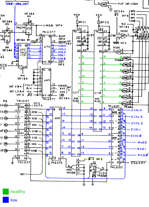
The data for U117 and U118 flows from another SRAM chip, a 93419 at U53. Its data out pins were all stuck high, but the data input pins looked healthy. WE never went low, so no data was being written to the chip.
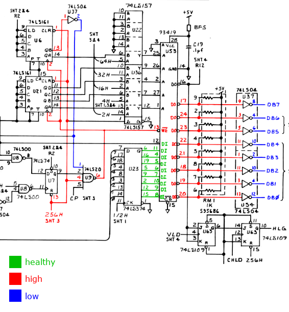
The WE signal is driven by a 4 input NAND gate at U9. In order for WE to go low, all 4 inputs to this gate must be high at the same time. The source of the issue was the input on pin 1, which was frozen low.
There is only one external input that drives this signal, labeled 256H. That signal was shorted directly to VCC, even without power. The schematics report that 256H derives from U50 pin 5.
Strangely, that pin had a healthy pulse and did not connect to the trace I was investigating. To solve this riddle, I recorded all the connections to the trace and cross referenced those with the schematics.
| Component | Pin | Part | Function | I/O | Schematic |
|---|---|---|---|---|---|
| U6 | 1 | LS161 | RST | IN | 256H sheet 2 |
| U7 | 13 | LS74 | CLR | IN | 256H sheet 2 |
| U9 | 4 | LS20 | C1 | IN | 256H sheet 2 |
| U21 | 1 | LS161 | RST | IN | 256H sheet 2 |
| U22 | 1 | LS157 | SEL | IN | 256H sheet 2 |
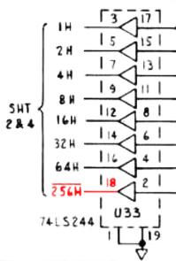
| U33 | 18 | LS244 | Y1 | OUT | 256H sheet 3 |
| U36 | 1 | LS157 | SEL | IN | 256H sheet 2 |
| U39 | 13 | LS139 | 2B | IN | 256H sheet 2 |
| U51 | 11 | LS374 | CLK | IN | 256H sheet 4 |
| U100 | 4 | LS08 | A2 | IN | 256H sheet 2 |
There is an error in the schematics. The correct name for this signal is 256H, and it comes from U33 pin 18.
At this point I had fixed everything obvious I found with the multimeter and logic probe, so I booted it back up.
This was progress, but it wasn't quite fixed. Sprites were missing!
Missing Sprites
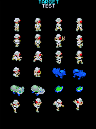
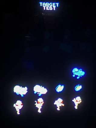
I placed both MAME and the PCB into test mode and navigated to the first sprite test screen. This provided a stable test environment with deterministic sprite memory that did not change from frame to frame. The pcb was failing to draw the first 15 sprites on all the test screens.
| MAME | PCB |
|---|---|
|
|
I was able to deduce the following information about the sprite DMA from the MAME source:
Once a frame, the sprite list is copied from CPU visible memory to sprite RAM
on the video board.

[c030:C031] = 16 bit word containing source address for sprite DMA
[c032]      = number of sprites to copy - 1
[c033]      = write of 1 to this address triggers the DMA

source address is always: 0x8401
maximum index is always : 0x1E

Each source element is 5 bytes and spaced at 32 byte intervals.
The input data is organized as:
[byte 0] = index
[byte 1] = x coordinate
[byte 2] = sprite number
[byte 3] = palette
[byte 4] = y coordinate
|
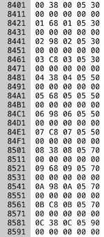
On the real hardware the sprite memory transfer is performed by the custom chip on the control board labeled G501564. I used a logic analyzer to spy on the pins of this chip and dumped the signals to a CSV. Then I wrote a program to reconstruct the captured signals into a set of read/write operations. I compared the output to the memory in MAME at 0x8401.
| MAME | G501564 |
|---|---|
|
RD 8401 00 RD 8402 38 WR 0000 38 RD 8403 00 WR 0001 00 RD 8404 05 WR 0002 05 RD 8405 30 WR 0003 30 RD 8421 01 RD 8422 68 WR 0004 68 RD 8423 01 WR 0005 01 RD 8424 05 WR 0006 05 RD 8425 30 WR 0007 30 RD 8441 02 RD 8442 98 WR 0008 98 RD 8443 02 WR 0009 02 RD 8444 05 WR 000a 05 RD 8445 30 WR 000b 30 RD 8461 03 RD 8462 c8 WR 000c c8 RD 8463 03 WR 000d 03 RD 8464 05 WR 000e 05 RD 8465 30 WR 000f 30 RD 8481 04 RD 8482 38 WR 0010 38 RD 8483 04 WR 0011 04 RD 8484 05 WR 0012 05 RD 8485 50 WR 0013 50 ... |
The custom G501564 chip was confirmed working. It loops through all the sprites at the source address, spaced every 32 bytes, and writes them to the destination RAM, tightly packed to 4 bytes. The data being copied perfectly matched the values observed in the MAME memory window.
The next item to investigate was the destination SRAM on the video board, where the sprite DMA is written. This is U12, a MB8128. I used the logic analyzer to spy on the data flowing through this chip and wrote a program to validate the values being written and read at each byte.
The table belows shows values written to the RAM chip at each address, and the values the RAM chip returned after it was subsequently read. The addresses where the chip returned data that did not match the expected written value are highlighted in red.
| 00 - 1F | 20 - 3F | 40-5F | 60-7B |
|---|---|---|---|
00 W: 38 R: 38 01 W: 00 R: 10 02 W: 05 R: 11 03 W: 30 R: 30 04 W: 68 R: 68 05 W: 01 R: 11 06 W: 05 R: 11 07 W: 30 R: 30 08 W: 98 R: 98 09 W: 02 R: 12 0a W: 05 R: 17 0b W: 30 R: b0 0c W: c8 R: c8 0d W: 03 R: 13 0e W: 05 R: 17 0f W: 30 R: b0 10 W: 38 R: 38 11 W: 04 R: 14 12 W: 05 R: 05 13 W: 50 R: 50 14 W: 68 R: 68 15 W: 05 R: 15 16 W: 05 R: 05 17 W: 50 R: d0 18 W: 98 R: 98 19 W: 06 R: 16 1a W: 05 R: 05 1b W: 50 R: d0 1c W: c8 R: c8 1d W: 07 R: 17 1e W: 05 R: 05 1f W: 50 R: 50 |
20 W: 38 R: f8
21 W: 08 R: 00
22 W: 05 R: 00
23 W: 70 R: 00
24 W: 68 R: ff
25 W: 09 R: 00
26 W: 05 R: 00
27 W: 70 R: 00
28 W: 98 R: 9f
29 W: 0a R: 00
2a W: 05 R: 00
2b W: 70 R: 00
2c W: c8 R: ff
2d W: 0b R: 00
2e W: 05 R: 00
2f W: 70 R: 00
30 W: 38 R: f8
31 W: 0c R: 00
32 W: 05 R: 00
33 W: 90 R: 00
34 W: 68 R: 6f
35 W: 0d R: 00
36 W: 05 R: 00
37 W: 90 R: 00
38 W: 98 R: ff
39 W: 0e R: 00
3a W: 11 R: 00
3b W: 90 R: 00
3c W: c8 R: c8
3d W: 0f R: 0f
3e W: 11 R: 11
3f W: 90 R: 90
| 40 W: 38 R: 38 41 W: 10 R: 10 42 W: 11 R: 11 43 W: b0 R: b0 44 W: 68 R: 68 45 W: 11 R: 11 46 W: 11 R: 11 47 W: b0 R: b0 48 W: 98 R: 98 49 W: 12 R: 12 4a W: 17 R: 17 4b W: b0 R: b0 4c W: c8 R: c8 4d W: 13 R: 13 4e W: 17 R: 17 4f W: b0 R: b0 50 W: 38 R: 38 51 W: 14 R: 14 52 W: 05 R: 05 53 W: d0 R: d0 54 W: 68 R: 68 55 W: 15 R: 15 56 W: 05 R: 05 57 W: d0 R: d0 58 W: 98 R: 98 59 W: 16 R: 16 5a W: 05 R: 05 5b W: d0 R: d0 5c W: c8 R: c8 5d W: 17 R: 17 5e W: 05 R: 05 5f W: d0 R: d0 | 60 W: ff R: ff 61 W: 00 R: 00 62 W: 00 R: 00 63 W: 00 R: 00 64 W: ff R: ff 65 W: 00 R: 00 66 W: 00 R: 00 67 W: 00 R: 00 68 W: ff R: ff 69 W: 00 R: 00 6a W: 00 R: 00 6b W: 00 R: 00 6c W: ff R: ff 6d W: 00 R: 00 6e W: 00 R: 00 6f W: 00 R: 00 70 W: ff R: ff 71 W: 00 R: 00 72 W: 00 R: 00 73 W: 00 R: 00 74 W: ff R: ff 75 W: 00 R: 00 76 W: 00 R: 00 77 W: 00 R: 00 78 W: ff R: ff 79 W: 00 R: 00 7a W: 00 R: 00 7b W: 00 R: 00 |
Problem found! These results also demonstrate why the first 15 sprites were missing; the malfunctioning addresses were all in the lower 64 bytes.
I replaced U12 with a new MB8128-10, and no more missing sprites!